FAQ
CLASSIFICATION
>Attributes
TAXONOMY
FORMATION
Wall collapse
DIMENSIONS
Components
Terminology
>Synopsis
MEASUREMENT
Kolob Arch
Rainbow Bridge
Triangulation
Hopewell Arch
IDENTIFICATION
REFERENCES
Measuring the Span of Hopewell Arch:
A Simple Method Using Laser Ranges and Anglesby Jay H. Wilbur
Laser range finders have truly revolutionized the measurement of natural arches. Not only are these devices extremely precise – my Leica Disto range finder has an advertised precision of a tenth of an inch for ranges up to 200 yards – they also allow measurements of points on an arch that would otherwise be difficult, if not impossible, to access.
In my article on measuring the span of an arch with laser triangulation, I described one way to use a laser range finder to find the span of an arch that is difficult to access. That method involves measuring all three sides of two triangles that share a horizontal base, and then calculating the distance between the vertices of the two triangles. A big advantage of that method is that it does not depend on any angle measurements. All the measurements taken are ranges. Typically, angle measurements are much less precise than laser range measurements.
However, it is not always necessary to avoid angle measurements. In cases where extreme precision is not particularly important, combining angle measurements with range measurements can make it pretty easy to measure an arch that would be very hard to measure if all you had with you was a tape. This article describes one way to do this. Because I applied this method to measure the span of Hopewell Arch in the Red River Gorge area of Kentucky, that arch is included here as an example.
The method described here can be summarized as follows:
- establish the axes of a reference coordinate system for measuring points on the arch,
- use range and angle measurements to find the spherical coordinates of the two key points on the arch that will determine the span,
- convert these spherical coordinates to Cartesian coordinates,
- calculate the span as the horizontal distance between the two points,
- estimate the precision of your measurement.
These steps require a basic knowledge of trigonometry. Each is described below using my measurement of Hopewell Arch as an example. You may also wish to review spherical coordinates at the following URL: http://mathworld.wolfram.com/SphericalCoordinates.html
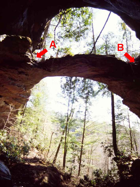
First, find a place where you can clearly see, and range to, the two key points on the arch that will determine its span. In the case of Hopewell Arch, these two points are indicated by arrows and the letters A and B in Figure 1.
Figure 1Set up your range finder on a tripod at a place where both are visible. Your tripod must be able to rotate the range finder in both elevation and azimuth. The center point of tripod rotation is going to be the origin of your reference coordinate system so let’s label it as point O. The vertical line passing through the center point of tripod rotation is the primary axis (the Z axis) of your reference coordinate system. The horizontal plane that passes through the center point of tripod rotation is the primary plane (the XY plane) of your reference coordinate system. See Figure 2 for a schematic.
Figure 2Next, determine which of the two points on the arch is farther from you. In our example it is point A. Use the azimuthal direction to point A as the secondary (X) axis of your reference coordinate system.
Now, use the range finder to measure the distance between points O and A. While pointing at A, measure the elevation angle of point A as seen from point O. I use a plumb bob tool to do this. Typically, elevation angles can be measured with a precision of about plus or minus one degree with this type of tool. We now have the three spherical coordinates of point A in our reference coordinate system. Remember that we defined this system so that the azimuthal angle of point A was zero.
Next, let’s call the closer point on the arch point B. Rotate the tripod horizontally and vertically so that the range finder points to it. The angle that the tripod rotates in the horizontal plane is the azimuth of point B. I use a protractor mounted on an axis of my tripod to measure azimuthal angles. This also results in angle measurements with a precision of about a degree. The angle that the tripod rotates vertically is the elevation of point B. Use the range finder to measure the distance between points O and B. We now have the three spherical coordinates of point B in our reference coordinate system.
When I used this method to measure Hopewell Arch, I actually did it from two different spots. The first spot I chose produced the following spherical coordinates for points A and B:
- Point A – range 37.8 ft, elevation 42º, azimuth 0º
- Point B – range 31.5 ft, elevation 65º, azimuth 95º
Next, we convert these measurements to Cartesian (XY) coordinates. Since the span of the arch is a horizontal dimension, we only need to compute the X and Y coordinates of points A and B. If we were determining the opening breadth, however, we would also need to compute the Z coordinates of these points. This is left as an exercise for those readers who are interested.
For point A, the X coordinate is the range times the cosine of the elevation. For my first measurement of Hopewell Arch, then, the X coordinate of point A is 37.8 ft times the cosine of 42º, or 28.1 ft. Since we set up our reference coordinate system so that the azimuth of point A would be zero, the Y coordinate of point A is also zero.
For point B things get a little more complicated. The X coordinate is the range times the cosine of the elevation times the cosine of the azimuth. For my first measurement of Hopewell Arch, the X coordinate of point B is 31.5 ft times cosine 65º times cosine 95º, or -1.2 ft. The Y coordinate is the range times the cosine of the elevation times the sine of the azimuth. For my first measurement of Hopewell Arch, the Y coordinate of point B is 31.5 ft times cosine 65º times sine 95º, or 13.3 ft.
We now have the Cartesian (X, Y) coordinates of points A and B. My first measurement of Hopewell Arch resulted in these numbers:
- Point A – X = 28.1 ft, Y = 0.0 ft
- Point B – X = -1.2 ft, Y = 13.3 ft
Now we can use the Pythagorean Theorem to compute the horizontal distance between the two points. This theorem states that the total distance between the two points is the square root of the sum of the squares of the separation in X and the separation in Y. For my first measurement of Hopewell Arch then, the separation in X is 29.3 ft, and the separation in Y is 13.3 ft. The square root of the sum of the squares of those two numbers is 32.5 ft. This is the span of the arch.
The final step is to estimate the precision of this result. Developing the equations for describing precision in the general case involves too much math for this article. Therefore, I am only going to estimate it here for the example, i.e., for Hopewell Arch.
Start by noting that the error in the two range measurements is insignificant compared to the error in the angle measurements. Because of this, we can get a good estimate of the precision of our results by re-computing them assuming each of the three angles we measured was off by one degree.
Go back and re-compute using an elevation angle of 41º for point A, an elevation angle of 64º for point B, and an azimuth of 96º for point B. The new span is 32.9 ft. This is different from our first computed span by 0.4 ft. Consequently, we can now report that the span of Hopewell Arch is 32.5 ± .4 feet.
One might note from the above that the error in angle measurements propagates into the final calculation in direct proportion to the range. This is why we used the further point (point A) to define our reference coordinate system. In that way, only one angle could blur the result of the further point, and the error in the two angles necessary to find the second point only propagate over the shorter range. Hence, our overall precision is improved versus using the nearer point (point B) to define the reference coordinate system.
Finally, it should be noted that this method can be made more precise by repeating the measurements from two or three different spots and using more sophisticated statistical analysis.